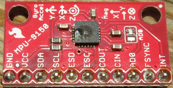
As the odour of fried electronics dissipates in the air, I’m unexpectedly afforded the opportunity to write this blog post a day or two earlier than planned. The on-board compass was exhibiting significant deviation, so I consulted my nephew Thorbjørn Christensen at DTU-Space. Thorbjørn makes a living designing magnetometers for space agencies around the world, and he suggested I use a ribbon cable to move the IMU away from the bot as a first step towards understanding the issue. He did warn me to be very careful when attaching it. I still don’t understand what I did wrong, but the evidence that I screwed up is pretty definitive: there are burn marks around every single connector and the IMU chip looks a bit soft in the middle. Most importantly, it no longer reports for duty on the Raspberry Pi’s I2C bus!
The good news (apart from the fact that the Raspberry Pi, the Arduino and all other ‘bot components seem to have survived) is perhaps that, since I cannot play with the compass until I have a replacement, I found the time to write about where I am at the moment…and take some time out to work on my presentations for Dyalog ’14 (for those who managed to register before the user meeting in Eastbourne sold out, I still hope to do a ‘bot presentation on the evening of Tuesday September 23rd).
Introducing the MPU-9150
For the last few weeks, I have been using my “bot time” to play with the MPU-9150 breakout board that is attached to our ‘bot. The MPU-9150 is more or less identical to the 6050 that we were using earlier this summer to make gyro-controlled turns but also includes a magnetic compass, which will allow us to know the direction that we are heading in – making it a 9 degree of freedom inertial measurement unit, or “9-dof IMU” (9 = 3 gyro axes + 3 accelerometer axes + 3 compass axes).
RTIMULib
I was extremely happy to discover that Richard Barnett had shared his RTIMULib on GitHub. RTIMULib is a Linux library that produces “Kalman-filtered quaternion or Euler angle pose data” based on data from a 9-dof IMU. Jay Foad at Dyalog was quickly able to provide me with a couple of additional C functions designed to be easy to call from Dyalog APL. Jay’s fork of RTIMULib is also available on GitHub. Since we can assume that we are driving on a flat surface, I have just been using two items from the wealth of information provided by this library: the current rate of rotation and the current compass direction – in both cases around the vertical (or “z”) axis.
My First Compass-Controlled Rotation
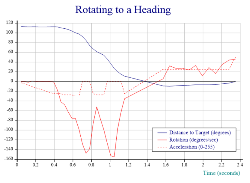
Due to the fried IMU, I am unable to post a video recording; fortunately, at the moment where I toasted the chip, the Dyalog session output still contained output data from the last run of the function I am working on, which aims to provide smooth rotation to a selected compass heading. In the chart below, the red line tracks the speed of rotation and shows that the “smooth” part still needs work – the speed oscillates quite violently between 60 and 150 degrees per second. The blue line shows the number of degrees that the ‘bot still needs to turn to reach the desired heading. The dotted red line is slightly mislabeled: rather than acceleration, it actually shows the power applied to the motors via a digital-to-analog converter that accepts values between 0 and 255, producing between 0 and 5v of voltage for the DC motors:
Commentary:
- From 0 to 0.4 seconds, we slowly increase power until we detect that rotation has started. We note the power setting required to start rotation.
- 0.4 to 0.7 (ish), we detect acceleration and hold the throttle steady (increasing it very slightly a couple of times when acceleration appears to stop).
- 0.7 to 1.1 seconds, cruise mode: whenever speed is above the target of 100 degrees/sec, we idle. When speed is below 100, we re-apply power at a level that was sufficient to start the rotation.
- 1.1 to 1.4 seconds: We are less than 30 degrees from target, and the target velocity and thus power is reduced proportional to the remaining distance (at 15 degrees, we are down to 50 deg/sec)
- 1.4 to 1.6 seconds: We detect that we rotated too far, and slam on the brakes, coming to a stop about 10 degrees from target.
- 1.6 to 2.3 seconds: since we are less than 10 degrees from target, we enter “step” mode, giving very brief bursts of power at “start rotation” level, idling, and watching the heading until we reach the goal.
- 2.4 seconds: We count the bursts and, after 10, we double the power setting to avoid getting bogged down (you cannot see the bursts in the chart, it only records the power level used for each one). A little more patience would have been good, this probably means we overshot by a bit.
The “Heading” Function
Achieving anything resembling smooth movement is still some way away, mostly due to the fact that motor response to a given input voltage varies enormously from motor to motor and between different applications to the same motor. The strategy described above is implemented by a function named “Heading”, which can be found in the file mpu9150.dyalog in the APLBot folder on GitHub. An obvious improvement would be to have the robot self-calibrate itself somehow and add a model of how fast rotation speeds up and slows down (based on, and constantly adjusted with, observed data), in order to dampen the oscillations. I intend to return to this when I have a new IMU (and my other user meeting presentations are under control).
This has turned out to be a lot harder than I imagined: suggestions are very welcome – please leave comments if you have a good idea!


 Follow